点击上方“3D视觉工坊”,选择“星标”
干货第一时间送达

作者丨李太白lx
来源丨从零开始搭SLAM
本篇文章将介绍两种新的传感器,IMU以及轮速计.
首先对这两种传感器进行简要介绍,之后对这两种传感器数据进行简单处理,之后对IMU,轮速计与激光雷达数据进行简单的时间同步,最后实现 使用这两个传感器进行单线激光雷达的运动畸变校正 的功能.
本文的代码的实现借鉴于LIO-SAM中的运动畸变校正部分.
1 IMU与轮速计的简介 1.1 IMU 1.1.1 简介IMU全称Inertial Measurement Unit,惯性测量单元,主要用来检测和测量加速度与旋转运动的传感器。
IMU一般包括3个功能,
-
3轴加速度计:测量 x y z 3个方向上的加速度,z轴的加速度也就是重力值的大小(IMU水平的情况下)
-
3轴陀螺仪(角度度计):测量出IMU分别绕着 x y z 轴旋转的角速度
-
3轴磁力计:测出地球磁场的方向,用于确定IMU 在 x y z 轴的方向,但是受磁铁,金属等影响较大.
前两个功能的组合被称为6轴IMU,这3个功能的组合被称为9轴IMU.
IMU的频率可以很高,10hz-400hz 不等.
1.1.2 ros中的消息格式IMU在ROS中的消息格式如下,有些IMU会提供积分后的姿态值,也就是orientation,有些不会提供,就需要自己通过对角速度进行积分来获取姿态值.
比较常用的是角速度与加速度这两项.
$ rosmsg show sensor_msgs/Imu


std_msgs/Header header    # 消息头
uint32 seq
  time stamp        # 时间戳
string frame_id      # 坐标系
geometry_msgs/Quaternion orientation    # IMU的当前姿态,4元数的形式表示
float64 x
float64 y
float64 z
float64 w
float64[9] orientation_covariance      # 姿态的协方差
geometry_msgs/Vector3 angular_velocity    # IMU的3轴角速度
float64 x
float64 y
float64 z
float64[9] angular_velocity_covariance    # IMU的3轴角速度的协方差
geometry_msgs/Vector3 linear_acceleration  # IMU的3轴加速度
float64 x
float64 y
float64 z
float64[9] linear_acceleration_covariance  # IMU的3轴加速度的协方差
1.2 轮速计 1.2.1 简介
轮速计就是安装在电机上的编码器,通过电机旋转的圈数来计算机器人所走过的距离与角度,在ROS中称为Odometry,译为里程计.
后来,随着SLAM的发展,里程计代表的意思多了起来,如激光雷达里程计,视觉里程计等等,这些代表的意思与轮速计差不多,都是通过各种方式,获取雷达或者相机这段时间内移动的距离与角度.
轮速计的频率一般不会太高,一般为20hz-50hz.
本文所用的里程计指的是轮速计,也就是通过编码器获取的距离与角度.
1.2.2 ros中的消息格式$ rosmsg show nav_msgs/Odometry
std_msgs/Header header
uint32 seq
time stamp # 时间戳
string frame_id # 里程计坐标系名字,一般为odom
string child_frame_id # 里程计坐标系指向的子坐标系名字,一般为base_link或者footprint
geometry_msgs/PoseWithCovariance pose # 带协方差的位姿
geometry_msgs/Pose pose
geometry_msgs/Point position # 位置,x y z
float64 x
float64 y
float64 z
geometry_msgs/Quaternion orientation # 四元数表示的姿态
float64 x
float64 y
float64 z
float64 w
float64[36] covariance
geometry_msgs/TwistWithCovariance twist # 带协方差的速度值
geometry_msgs/Twist twist
geometry_msgs/Vector3 linear # 线速度
float64 x
float64 y
float64 z
geometry_msgs/Vector3 angular # 角速度
float64 x
float64 y
float64 z
float64[36] covariance
里程计中也存在线速度角速度,但是这个线速度角速度是通过距离除以时间得到的,没有IMU的精确.
大多数情况下,优先使用IMU的角速度,与轮速计的距离值.
2 代码讲解 2.1 获取代码代码已经提交在github上了,github的地址为 https://github.com/xiangli0608/Creating-2D-laser-slam-from-scratch
推荐使用 git clone 的方式进行下载, 因为代码是正处于更新状态的, git clone 下载的代码可以使用 git pull 很方便地进行更新.
本篇文章对应的代码为
Creating-2D-laser-slam-from-scratch/lesson5/src/lidar_undistortion.cc
Creating-2D-laser-slam-from-scratch/lesson5/include/lesson5/lidar_undistortion.h
2.2 回调函数由于使用了3个线程,所以在保存imu与odom数据时,需要先上锁,以防止同一时间有2个地方对imu_queue_ 与 odom_queue_ 进行更改.
// imu的回调函数
void LidarUndistortion::ImuCallback(const sensor_msgs::Imu::ConstPtr &imuMsg)
{
std::lock_guardlock(imu_lock_);
    imu_queue_.push_back(*imuMsg);
}


// odom的回调函数
void LidarUndistortion::OdomCallback(const nav_msgs::Odometry::ConstPtr &odometryMsg)
{
std::lock_guardlock(odom_lock_);
    odom_queue_.push_back(*odometryMsg);
}


// scan的回调函数
void LidarUndistortion::ScanCallback(const sensor_msgs::LaserScan::ConstPtr &laserScanMsg)
{
// 缓存雷达数据
if (!CacheLaserScan(laserScanMsg))
return;


// 如果使用imu,就对imu的数据进行修剪,进行时间同步,并计算雷达数据时间内的旋转
if (use_imu_)
    {
if (!PruneImuDeque())
return;
    }


// 如果使用odom,就对odom的数据进行修剪,进行时间同步,并计算雷达数据时间内的平移
if (use_odom_)
    {
if (!PruneOdomDeque())
return;
    }


// 对雷达数据的每一个点进行畸变的去除
    CorrectLaserScan();


// 将较正过的雷达数据以PointCloud2的形式发布出去
    PublishCorrectedPointCloud();


// 参数重置
    ResetParameters();
}
2.3 缓存雷达数据
通过双端队列进行雷达数据的保存,并且确保队列中至少有2个数据,以防止imu或者odom的数据时间不能包含雷达数据的时间.
之后,获取了current_laserscan_的时间戳,以及点云结束的时间戳.
// 缓存雷达数据
bool LidarUndistortion::CacheLaserScan(const sensor_msgs::LaserScan::ConstPtr &laserScanMsg)
{
if (first_scan_)
    {
        first_scan_ = false;


// 雷达数据间的角度是固定的,因此可以将对应角度的cos与sin值缓存下来,不用每次都计算
        CreateAngleCache(laserScanMsg);


        scan_count_ = laserScanMsg->ranges.size();
    }


    corrected_pointcloud_->points.resize(laserScanMsg->ranges.size());


// 缓存雷达数据
    laser_queue_.push_back(*laserScanMsg);


// 缓存两帧雷达数据,以防止imu或者odom的数据不能包含雷达数据
if (laser_queue_.size() < 2)
return false;


// 取出队列中的第一个数据
    current_laserscan_ = laser_queue_.front();
    laser_queue_.pop_front();


// 获取这帧雷达数据的起始,结束时间
    current_laserscan_header_ = current_laserscan_.header;
    current_scan_time_start_ = current_laserscan_header_.stamp.toSec(); // 认为ros中header的时间为这一帧雷达数据的起始时间
    current_scan_time_increment_ = current_laserscan_.time_increment;
    current_scan_time_end_ = current_scan_time_start_ + current_scan_time_increment_ * (scan_count_ - 1);


return true;
}
2.4 IMU的时间同步与角度积分
由于是使用双端队列进行IMU数据的存储,所以,队列中IMU的时间是连续的.
同时由于IMU是100hz的,而雷达是10hz的,二者频率不同,时间戳也就对不上,所以需要做一下时间同步.
时间同步的思想就是,先将imu的双端队列中时间太早的数据删去.
之后找到IMU的时间与当前帧雷达的起始时间早的第一个IMU数据.
以这个IMU数据作为起点,使用之后的IMU数据进行积分,分别获得2个IMU数据之间的旋转,imu_rot_x_ 保存的是当前时刻相对于第一帧imu数据时刻,转动的角度值.
重复这个操作,直到IMU的时间戳比当前帧雷达数据旋转一周之后的时间要晚.也就是这些IMU数据的时间是包含了雷达数据转一圈的时间.
// 修剪imu队列,以获取包含 当前帧雷达时间 的imu数据及转角
bool LidarUndistortion::PruneImuDeque()
{
std::lock_guardlock(imu_lock_);


// imu数据队列的头尾的时间戳要在雷达数据的时间段外
if (imu_queue_.empty() ||
        imu_queue_.front().header.stamp.toSec() > current_scan_time_start_ ||
        imu_queue_.back().header.stamp.toSec() < current_scan_time_end_)
    {
        ROS_WARN("Waiting for IMU data ...");
return false;
    }


// 修剪imu的数据队列,直到imu的时间接近这帧点云的时间
while (!imu_queue_.empty())
    {
if (imu_queue_.front().header.stamp.toSec() < current_scan_time_start_ - 0.1)
            imu_queue_.pop_front();
else
break;
    }


if (imu_queue_.empty())
return false;


    current_imu_index_ = 0;


    sensor_msgs::Imu tmp_imu_msg;
double current_imu_time, time_diff;


for (int i = 0; i < (int)imu_queue_.size(); i++)
    {
        tmp_imu_msg = imu_queue_[i];
        current_imu_time = tmp_imu_msg.header.stamp.toSec();


if (current_imu_time < current_scan_time_start_)
        {
// 初始角度为0
if (current_imu_index_ == 0)
            {
                imu_rot_x_[0] = 0;
                imu_rot_y_[0] = 0;
                imu_rot_z_[0] = 0;
                imu_time_[0] = current_imu_time;
                ++current_imu_index_;
            }
continue;
        }


// imu时间比雷达结束时间晚,就退出
if (current_imu_time > current_scan_time_end_)
break;


// get angular velocity
double angular_x, angular_y, angular_z;
        angular_x = tmp_imu_msg.angular_velocity.x;
        angular_y = tmp_imu_msg.angular_velocity.y;
        angular_z = tmp_imu_msg.angular_velocity.z;


// 对imu的角速度进行积分,当前帧的角度 = 上一帧的角度 + 当前帧角速度 * (当前帧imu的时间 - 上一帧imu的时间)
double time_diff = current_imu_time - imu_time_[current_imu_index_ - 1];
        imu_rot_x_[current_imu_index_] = imu_rot_x_[current_imu_index_ - 1] + angular_x * time_diff;
        imu_rot_y_[current_imu_index_] = imu_rot_y_[current_imu_index_ - 1] + angular_y * time_diff;
        imu_rot_z_[current_imu_index_] = imu_rot_z_[current_imu_index_ - 1] + angular_z * time_diff;
        imu_time_[current_imu_index_] = current_imu_time;
        ++current_imu_index_;
    }


// 对current_imu_index_进行-1操作后,current_imu_index_指向当前雷达时间内的最后一个imu数据
    --current_imu_index_;


return true;
}
2.5 轮速计的时间同步与平移计算
轮速计的时间同步方式与IMU的基本一致,只是由于轮速计是固定坐标系下的位姿变换,所以不需要由我们自己对每一帧数据进行积分.
直接找到雷达数据开始前的一帧odom数据,与雷达旋转一圈之后的一帧odom数据,求这两个odom数据之间的坐标变换,即可得到雷达旋转一圈时间附近的总平移量.
// 修剪imu队列,以获取包含 当前帧雷达时间 的odom的平移距离
bool LidarUndistortion::PruneOdomDeque()
{
std::lock_guardlock(odom_lock_);


// imu数据队列的头尾的时间戳要在雷达数据的时间段外
if (odom_queue_.empty() ||
        odom_queue_.front().header.stamp.toSec() > current_scan_time_start_ ||
        odom_queue_.back().header.stamp.toSec() < current_scan_time_end_)
    {
        ROS_WARN("Waiting for Odometry data ...");
return false;
    }


// 修剪odom的数据队列,直到odom的时间接近这帧点云的时间
while (!odom_queue_.empty())
    {
if (odom_queue_.front().header.stamp.toSec() < current_scan_time_start_ - 0.1)
            odom_queue_.pop_front();
else
break;
    }


if (odom_queue_.empty())
return false;


// get start odometry at the beinning of the scan
double current_odom_time;


for (int i = 0; i < (int)odom_queue_.size(); i++)
    {
        current_odom_time = odom_queue_[i].header.stamp.toSec();


if (current_odom_time < current_scan_time_start_)
        {
            start_odom_msg_ = odom_queue_[i];
continue;
        }


if (current_odom_time <= current_scan_time_end_)
        {
            end_odom_msg_ = odom_queue_[i];
        }
else
break;
    }


// if (int(round(start_odom_msg_.pose.covariance[0])) != int(round(end_odom_msg_.pose.covariance[0])))
//     return false;


    start_odom_time_ = start_odom_msg_.header.stamp.toSec();
    end_odom_time_ = end_odom_msg_.header.stamp.toSec();


    tf::Quaternion orientation;
double roll, pitch, yaw;


// 获取起始odom消息的位移与旋转
    tf::quaternionMsgToTF(start_odom_msg_.pose.pose.orientation, orientation);
    tf::Matrix3x3(orientation).getRPY(roll, pitch, yaw);


    Eigen::Affine3f transBegin = pcl::getTransformation(
        start_odom_msg_.pose.pose.position.x,
        start_odom_msg_.pose.pose.position.y,
        start_odom_msg_.pose.pose.position.z,
        roll, pitch, yaw);


// 获取终止odom消息的位移与旋转
    tf::quaternionMsgToTF(end_odom_msg_.pose.pose.orientation, orientation);
    tf::Matrix3x3(orientation).getRPY(roll, pitch, yaw);


    Eigen::Affine3f transEnd = pcl::getTransformation(
        end_odom_msg_.pose.pose.position.x,
        end_odom_msg_.pose.pose.position.y,
        end_odom_msg_.pose.pose.position.z,
        roll, pitch, yaw);


// 求得这之间的变换
    Eigen::Affine3f transBt = transBegin.inverse() * transEnd;


// 通过 transBt 获取 odomIncreX等,一帧点云数据时间的odom变化量
float rollIncre, pitchIncre, yawIncre;
    pcl::getTranslationAndEulerAngles(transBt,
                                      odom_incre_x_, odom_incre_y_, odom_incre_z_,
                                      rollIncre, pitchIncre, yawIncre);
return true;
}
2.6 对雷达数据的每个点进行畸变校正
文字说明如何进行畸变校正
目前的单线激光雷达只有一个单点激光发射器,通过旋转反射镜或者旋转激光发射器一周,实现了360度范围的扫描.
而由于这一周的激光点数据不是同一时间得到的,就导致了雷达数据会在雷达发生运动时雷达数据会产生运动畸变.
举个例子一个360的单线激光雷达,发射第一个点时激光雷达的位置是在(1, 0)处,碰到物体反射回来,测得的距离值为1.3m.由于激光雷达处于前进的状态,激光器旋转一周后,发射最后一个点时激光雷达的位置时假设变成了(1.1, 0),再次碰到上述物体反射回来,测得的距离值就变为了1.2m.
而一般的激光雷达驱动是不会对这种现象进行处理的,最终得到的数据也就变成了,激光雷达处于(1, 0)位置处,观测前方1.3m的物体,雷达数据的第一个点返回的值为1.3m,而雷达数据的最后一个点测得的相同物体的距离为1.2m.
这就是畸变的发生的原理,是由于不同时刻,获取距离值时的激光雷达的坐标系发生了变化导致的.
如何进行畸变校正知道了畸变是如何发生的,那如何进行畸变校正就清晰了.
只需要找到每个激光点对应时刻的激光雷达坐标系,相对于发射第一个点时刻的激光雷达坐标系,间的坐标变换,就可以将每个激光点都变换到发射第一个点时刻的激光雷达坐标系下,就完成了畸变的校正.
首先,假设雷达发射第一个点的时刻为 time_start,这时的雷达坐标系为 frame_start.
雷达其余点的时刻为 time_point,这时的雷达坐标系为 frame_point,其余点在 frame_point 坐标系下的坐标为 point.
只需要找到 frame_start 与 frame_point 间的坐标变换,就可以将 其余点的坐标 point 通过坐标变换 变换到 frame_start 坐标系下.
对所有点都进行上述操作后,得到的点的坐标,就是去畸变后的坐标了.
这就是畸变校正的过程.
畸变校正的代码实现代码的实现和上述文字是一样的,就不再细说了.
// 对雷达数据的每一个点进行畸变的去除
void LidarUndistortion::CorrectLaserScan()
{
bool first_point_flag = true;
double current_point_time = 0;
double current_point_x = 0, current_point_y = 0, current_point_z = 1.0;


    Eigen::Affine3f transStartInverse, transFinal, transBt;


for (int i = 0; i < scan_count_; i++)
    {
// 如果是无效点,就跳过
if (!std::isfinite(current_laserscan_.ranges[i]) ||
            current_laserscan_.ranges[i] < current_laserscan_.range_min ||
            current_laserscan_.ranges[i] > current_laserscan_.range_max)
continue;


// 畸变校正后的数据
        PointT &point_tmp = corrected_pointcloud_->points[i];


        current_point_time = current_scan_time_start_ + i * current_scan_time_increment_;


// 计算雷达数据的 x y 坐标
        current_point_x = current_laserscan_.ranges[i] * a_cos_[i];
        current_point_y = current_laserscan_.ranges[i] * a_sin_[i];


float rotXCur = 0, rotYCur = 0, rotZCur = 0;
float posXCur = 0, posYCur = 0, posZCur = 0;


// 求得当前点对应时刻 相对于start_odom_time_ 的平移与旋转
if (use_imu_)
            ComputeRotation(current_point_time, &rotXCur, &rotYCur, &rotZCur);
if (use_odom_)
            ComputePosition(current_point_time, &posXCur, &posYCur, &posZCur);


// 雷达数据的第一个点对应时刻 相对于start_odom_time_ 的平移与旋转,之后在这帧数据畸变过程中不再改变
if (first_point_flag == true)
        {
            transStartInverse = (pcl::getTransformation(posXCur, posYCur, posZCur,
                                                        rotXCur, rotYCur, rotZCur))
                                    .inverse();
            first_point_flag = false;
        }


// 当前点对应时刻 相对于start_odom_time_ 的平移与旋转
        transFinal = pcl::getTransformation(posXCur, posYCur, posZCur,
                                            rotXCur, rotYCur, rotZCur);


// 雷达数据的第一个点对应时刻的激光雷达坐标系 到 雷达数据当前点对应时刻的激光雷达坐标系 间的坐标变换
        transBt = transStartInverse * transFinal;


// 将当前点的坐标 加上 两个时刻坐标系间的坐标变换
// 得到 当前点在 雷达数据的第一个点对应时刻的激光雷达坐标系 下的坐标
        point_tmp.x = transBt(0, 0) * current_point_x + transBt(0, 1) * current_point_y + transBt(0, 2) * current_point_z + transBt(0, 3);
        point_tmp.y = transBt(1, 0) * current_point_x + transBt(1, 1) * current_point_y + transBt(1, 2) * current_point_z + transBt(1, 3);
        point_tmp.z = transBt(2, 0) * current_point_x + transBt(2, 1) * current_point_y + transBt(2, 2) * current_point_z + transBt(2, 3);
    }
}
2.6.1 获取这个时刻的旋转
ComputeRotation() 这个函数返回的旋转值,是pointTime 相对于 比当前帧雷达数据时间早的第一个imu数据的时间 产生的总的旋转量.
// 根据点云中某点的时间戳赋予其 通过插值 得到的旋转量
void LidarUndistortion::ComputeRotation(double pointTime, float *rotXCur, float *rotYCur, float *rotZCur)
{
    *rotXCur = 0;
    *rotYCur = 0;
    *rotZCur = 0;


// 找到在 pointTime 之后的imu数据
int imuPointerFront = 0;
while (imuPointerFront < current_imu_index_)
    {
if (pointTime < imu_time_[imuPointerFront])
break;
        ++imuPointerFront;
    }


// 如果上边的循环没进去或者到了最大执行次数,则只能近似的将当前的旋转 赋值过去
if (pointTime > imu_time_[imuPointerFront] || imuPointerFront == 0)
    {
        *rotXCur = imu_rot_x_[imuPointerFront];
        *rotYCur = imu_rot_y_[imuPointerFront];
        *rotZCur = imu_rot_z_[imuPointerFront];
    }
else
    {
int imuPointerBack = imuPointerFront - 1;


// 根据线性插值计算 pointTime 时刻的旋转
double ratioFront = (pointTime - imu_time_[imuPointerBack]) / (imu_time_[imuPointerFront] - imu_time_[imuPointerBack]);
double ratioBack = (imu_time_[imuPointerFront] - pointTime) / (imu_time_[imuPointerFront] - imu_time_[imuPointerBack]);


        *rotXCur = imu_rot_x_[imuPointerFront] * ratioFront + imu_rot_x_[imuPointerBack] * ratioBack;
        *rotYCur = imu_rot_y_[imuPointerFront] * ratioFront + imu_rot_y_[imuPointerBack] * ratioBack;
        *rotZCur = imu_rot_z_[imuPointerFront] * ratioFront + imu_rot_z_[imuPointerBack] * ratioBack;
    }
}
2.6.2 获取这个时刻的平移
雷达数据的畸变产生主要是由于旋转产生的,由平移产生的畸变比较少.而且轮速计的频率一般不会很高.
所以这里就直接用雷达数据前后的轮速计的坐标差当做这段的平移量了,没有对雷达旋转时间范围内的每个值进行保存.
用线性插值计算了pointTime时刻的平移量.
// 根据点云中某点的时间戳赋予其 通过插值 得到的平移量
void LidarUndistortion::ComputePosition(double pointTime, float *posXCur, float *posYCur, float *posZCur)
{
    *posXCur = 0;
    *posYCur = 0;
    *posZCur = 0;


// 根据线性插值计算 pointTime 时刻的旋转
double ratioFront = (pointTime - start_odom_time_) / (end_odom_time_ - start_odom_time_);


    *posXCur = odom_incre_x_ * ratioFront;
    *posYCur = odom_incre_y_ * ratioFront;
    *posZCur = odom_incre_z_ * ratioFront;
}
3 运行
3.1 运行
本篇文章对应的数据包, 请在网盘获得
https://pan.baidu.com/s/10qKKVsp–iCQ7B1JPec0BQ 提取码:v332
下载之后将launch中的bag_filename更改成您实际的目录名。
通过如下命令运行本篇文章对应的程序
roslaunch lesson5 lidar_undistortion.launch3.2 运行结果与分析
启动之后,会在rviz中显示出如下画面.
 画面中的黄色点云就是畸变之后的点云.
如果想要看原始点云就把左侧的 LaserScan 右边的空白方框点一下,会出现红色的点云,是原始数据.
在录数据的时候,在走廊的交叉口处以0.8rad/s的角速度进行了长时间的旋转,以检测畸变校正后的点云的效果,如下图片就是旋转时的截图.
红色是原始雷达数据,黄色是畸变校正后的点云数据.
机器人运动的挺快的,如果看不清楚,可以在终端中里 按空格 , 暂停播放bag文件,以观察雷达数据的状态.
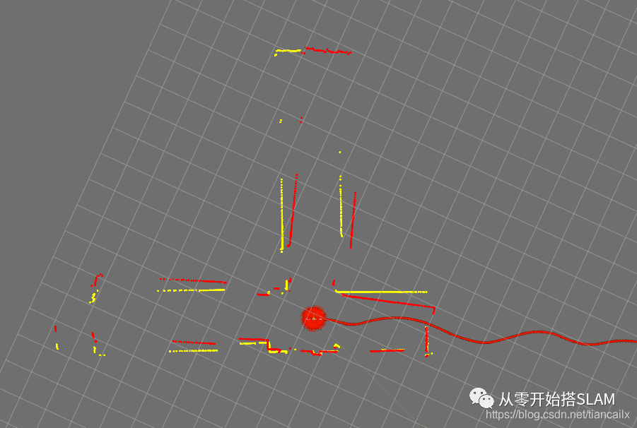
 可以看到,畸变校正的效果还是很明显的,在旋转时的雷达数据明显地变得整齐了.
在机器人主要进行平移运动时,产生的畸变比较小,所以畸变校正后的效果也不明显.
4 总结与Next本篇文章首先简要介绍了IMU与轮速计两种传感器,在代码中展示了如何对这两种传感器数据进行简单处理,进行了IMU,Odom,与雷达数据的时间同步,并使用这两种传感器进行了雷达数据的运动畸变校正.
通过仔细观察校正前后的点云效果,可以发现,在旋转时激光雷达的畸变尤其明显.
如果雷达只进行平移运动,畸变前后的数据差别不大.
不知道同学们有没有过这种经历,就是使用开源算法建图的过程中,如果旋转快了就会出现叠图的现象,这就是由于旋转时激光雷达的数据畸变严重导致的.
下篇文章将使用IMU与轮速计和激光雷达,共同进行前端里程计的实现.将基于Karto进行代码的编写,并使用滑动窗口保存一小块地图.
这也是本系列文章的最后一个前端的实现.
由于本人水平有限,难免会有些代码上的错误,如果您发现了错误或者不好的地方,请联系我,我会改正.
本文仅做学术分享,如有侵权,请联系删文。
干货下载与学习
后台回复:巴塞罗那自治大学课件,即可下载国外大学沉淀数年3D Vison精品课件
后台回复:计算机视觉书籍,即可下载3D视觉领域经典书籍pdf
后台回复:3D视觉课程,即可学习3D视觉领域精品课程
3D视觉工坊精品课程官网:3dcver.com
1.面向自动驾驶领域的多传感器数据融合技术
2.面向自动驾驶领域的3D点云目标检测全栈学习路线!(单模态+多模态/数据+代码) 3.彻底搞透视觉三维重建:原理剖析、代码讲解、及优化改进 4.国内首个面向工业级实战的点云处理课程 5.激光-视觉-IMU-GPS融合SLAM算法梳理和代码讲解 6.彻底搞懂视觉-惯性SLAM:基于VINS-Fusion正式开课啦 7.彻底搞懂基于LOAM框架的3D激光SLAM: 源码剖析到算法优化 8.彻底剖析室内、室外激光SLAM关键算法原理、代码和实战(cartographer+LOAM +LIO-SAM)
9.从零搭建一套结构光3D重建系统[理论+源码+实践]
10.单目深度估计方法:算法梳理与代码实现
11.自动驾驶中的深度学习模型部署实战
12.相机模型与标定(单目+双目+鱼眼)
13.重磅!四旋翼飞行器:算法与实战
14.ROS2从入门到精通:理论与实战
15.国内首个3D缺陷检测教程:理论、源码与实战
16.基于Open3D的点云处理入门与实战教程
重磅!3DCVer-学术论文写作投稿 交流群已成立
扫码添加小助手微信,可申请加入3D视觉工坊-学术论文写作与投稿 微信交流群,旨在交流顶会、顶刊、SCI、EI等写作与投稿事宜。
同时也可申请加入我们的细分方向交流群,目前主要有3D视觉、CV&深度学习、SLAM、三维重建、点云后处理、自动驾驶、多传感器融合、CV入门、三维测量、VR/AR、3D人脸识别、医疗影像、缺陷检测、行人重识别、目标跟踪、视觉产品落地、视觉竞赛、车牌识别、硬件选型、学术交流、求职交流、ORB-SLAM系列源码交流、深度估计等微信群。
一定要备注:研究方向+学校/公司+昵称,例如:”3D视觉 + 上海交大 + 静静“。请按照格式备注,可快速被通过且邀请进群。原创投稿也请联系。

▲长按加微信群或投稿,加微信:dddvision

▲长按关注公众号
3D视觉从入门到精通知识星球:针对3D视觉领域的视频课程(三维重建系列、三维点云系列、结构光系列、手眼标定、相机标定、激光/视觉SLAM、自动驾驶等)、知识点汇总、入门进阶学习路线、最新paper分享、疑问解答五个方面进行深耕,更有各类大厂的算法工程人员进行技术指导。与此同时,星球将联合知名企业发布3D视觉相关算法开发岗位以及项目对接信息,打造成集技术与就业为一体的铁杆粉丝聚集区,近4000星球成员为创造更好的AI世界共同进步,知识星球入口:
学习3D视觉核心技术,扫描查看介绍,3天内无条件退款

圈里有高质量教程资料、答疑解惑、助你高效解决问题
觉得有用,麻烦给个赞和在看~